Laboratory Overview
This introductory laboratory provides students with their first hands-on experience with edge AI hardware platforms. Through observation and familiarization activities, you will develop an understanding of the NVIDIA Jetson Orin Nano Developer Kit—the powerful AI computing platform you'll use throughout the semester. By comparing different hardware options and examining the JetBot robot system, you'll gain insight into why specific platforms are chosen for AI and robotics applications.
What You'll Learn
- Platform Selection Criteria: Understand the trade-offs between Arduino, Raspberry Pi, and Jetson platforms
- Edge AI Concepts: Learn why processing AI at the edge offers advantages over cloud computing
- Jetson Architecture: Identify the GPU, CPU, memory, storage, and connectivity components
- System Integration: See how motors, cameras, sensors, and compute platforms work together
- Component Functions: Understand the role of each part in the complete robot system
- Real-world Applications: Connect hardware capabilities to practical AI use cases
💡 Why This Matters
Hardware selection is the foundation of every successful AI project. Choosing the wrong platform can mean insufficient processing power, excessive power consumption, or unnecessary costs. The Jetson Orin Nano represents the sweet spot for edge AI—powerful enough for real-time deep learning inference, yet compact and power-efficient enough for mobile robotics. Understanding this platform and how it compares to alternatives will inform your design decisions in future projects, both in this course and in your engineering career.
Lab Structure
This laboratory consists of four observational and discussion-based parts designed to build your hardware knowledge:
- Part A (10 min): Platform Comparison Discussion
- Compare Arduino, Raspberry Pi, and Jetson Orin Nano specifications
- Identify appropriate applications for each platform
- Discuss cost, power, and performance trade-offs
- Part B (15 min): Component Identification
- Locate and identify major Jetson components
- Understand the function of GPIO pins, camera connectors, and storage
- Create a labeled diagram of the developer kit
- Part C (20 min): Assembly Process Review
- Observe the pre-assembled JetBot system
- Review assembly steps through visual walkthrough
- Understand component integration and wiring
- Part D (15 min): System Demonstration
- Watch instructor demonstrate boot process and basic operations
- Observe camera, motor, and display functionality
- Document system capabilities for future reference
Learning Objectives
By the end of this laboratory session, you will be able to:
- Compare and contrast different hardware platforms (Arduino, Raspberry Pi, and Jetson Orin Nano) for embedded systems and AI applications, understanding their respective strengths and limitations.
- Identify and explain the major components of the NVIDIA Jetson Orin Nano Developer Kit, including the GPU architecture, CPU cores, memory, storage, and connectivity options.
- Understand the concept of Edge AI computing and its advantages over cloud-based AI processing, including reduced latency, enhanced privacy, and improved reliability.
- Recognize the assembly components of the JetBot robot platform and understand how each part contributes to the overall system functionality.
- Appreciate the importance of proper hardware selection for AI and robotics projects, considering factors such as computational power, power consumption, size, and cost.
- Gain familiarity with the JetBot system that you will use throughout the semester for various AI and machine learning experiments.
Background
Hardware Platforms for AI and Embedded Systems
Selecting the right hardware platform is crucial for AI and embedded systems applications. The choice depends on computational requirements, power constraints, real-time processing needs, and the complexity of AI models to be deployed. In this course, we explore three major categories of platforms, each serving different purposes in the embedded systems and AI landscape.
Platform Comparison
| Feature | Arduino | Raspberry Pi | Jetson Orin Nano |
|---|---|---|---|
| Type | Microcontroller | Single Board Computer | AI Edge Computer |
| Processor | AVR/ARM Cortex-M | ARM Cortex-A72/A76 | 6-core ARM Cortex-A78AE |
| GPU | None | VideoCore VI (500MHz) | 1024-core Ampere GPU |
| RAM | 2KB-256KB SRAM | 1GB-8GB LPDDR4 | 8GB LPDDR5 |
| Storage | 32KB-512KB Flash | MicroSD Card | NVMe SSD (M.2) |
| OS Support | None (Bare Metal) | Linux, Windows IoT | Ubuntu (L4T), JetPack SDK |
| AI Performance | Not Applicable | Basic ML models | 40 TOPS |
| GPIO Pins | 14-54 pins | 40 pins | 40 pins |
| Networking | Optional shields | WiFi, Bluetooth, Ethernet | WiFi, Bluetooth, GbE |
| Display Output | None (LCD shields) | 2x micro HDMI | DisplayPort |
| Camera Support | Basic sensors only | CSI, USB cameras | 2x MIPI CSI-2, USB3 |
| USB Ports | 1 (for programming) | 2x USB 3.0, 2x USB 2.0 | 4x USB 3.2 |
| ML Frameworks | TinyML only | TensorFlow Lite, PyTorch | TensorFlow, PyTorch, TensorRT |
| Programming | C/C++, Arduino IDE | Python, C++, Java, etc. | Python, C++, CUDA |
| Real-time OS | Yes (FreeRTOS) | No (can add RT kernel) | No (can add RT kernel) |
| Power Input | 5V USB/7-12V DC | 5V USB-C | 9-20V DC barrel |
| Power Consumption | 0.05-0.5W | 2-6W | 7-15W |
| Size | ~68×53mm | 85×56mm | 100×79mm |
| Cost Range | $10-50 | $35-180 | $499 |
| Best Use Case | Sensors, Motors, LEDs | IoT, Media Center, Server | AI/ML, Robotics, Vision |
🔥 NVIDIA Jetson Orin Nano Specifications
The Jetson Orin Nano Developer Kit is the centerpiece of our AI laboratory, offering exceptional performance for edge AI applications:
- GPU: 1024-core NVIDIA Ampere architecture GPU with 32 Tensor Cores
- CPU: 6-core ARM Cortex-A78AE v8.2 64-bit CPU
- Memory: 8GB 128-bit LPDDR5
- Storage: Support for NVMe SSD via M.2 connector
- Video: 1080p30 supported encode and decode
- Camera: 2x MIPI CSI-2 D-PHY lanes
- Connectivity: Gigabit Ethernet, M.2 Key E, 4x USB 3.2
Edge AI and Real-time Processing
Edge AI computing brings artificial intelligence directly to IoT devices and embedded systems, enabling intelligent decision-making at the source of data generation rather than in the cloud. This approach offers several critical advantages:
- Low Latency: Process data locally without cloud round-trips, enabling real-time response for applications like autonomous vehicles and robotics
- Privacy: Keep sensitive data on-device, ensuring user privacy and compliance with data protection regulations
- Reliability: Operate independently without internet connectivity, crucial for remote or critical applications
- Efficiency: Reduce bandwidth requirements and cloud computing costs by processing data at the edge
Pre-lab Preparation
Before beginning the lab session, please watch the following video lectures and read the documentation. These materials provide essential background on hardware platforms and edge AI computing that will directly support your understanding during the laboratory activities.
📺 Video Lectures
📺 Required Viewing
Watch the following videos before the lab session:
✅ Pre-lab Quiz (MCQs)
Instructions: Test your understanding after watching the videos. Click on an answer to see if it's correct. These questions will also be answered in detail in your lab report.
Question 1: What is the primary difference between a microcontroller (like Arduino) and a single-board computer (like Raspberry Pi)?
Question 2: How many Tensor Cores does the Jetson Orin Nano GPU have?
Question 3: What is the AI performance rating (in TOPS) of the Jetson Orin Nano?
Question 4: Which of the following is NOT an advantage of Edge AI computing?
Question 5: What type of storage does the Jetson Orin Nano use in our lab configuration?
Question 6: What is the main reason for choosing Jetson Orin Nano over Raspberry Pi for AI applications?
Question 7: How much RAM does the Jetson Orin Nano Developer Kit have?
Question 8: Which platform would be most appropriate for a simple temperature monitoring system with LED indicators?
📝 Lab Report Requirement
In your lab report, you must provide detailed written answers to the following questions (not just multiple choice):
- Explain the key differences between microcontrollers, single-board computers, and AI edge computers. When would you choose each?
- What are Tensor Cores and why are they important for AI acceleration on the Jetson Orin Nano?
- Define Edge AI and explain its four main advantages over cloud-based AI processing.
- Why is NVMe SSD storage preferred over SD cards for AI applications on the Jetson platform?
- Compare the computational capabilities of Arduino, Raspberry Pi, and Jetson Orin Nano in terms of their suitability for real-time AI inference.
Laboratory Procedure
⏱️ Lab Duration: 60 minutes
This is an observational and familiarization laboratory. The Jetson Orin Nano JetBot has been pre-assembled and configured for you. Your goal is to understand the components, assembly process, and capabilities of the system that you will use throughout the semester.
Part A: Platform Comparison Discussion (10 minutes)
Using the comparison table from the Background section, work with your lab partner to discuss the following:
- For each platform (Arduino, Raspberry Pi, Jetson Orin Nano), identify two real-world applications where that platform would be the best choice.
- Explain why each platform is suited for those applications based on its specifications.
- Consider: What are the trade-offs between cost, power consumption, and computational capability?
Part B: Jetson Orin Nano Component Identification (15 minutes)
Observe the assembled Jetson Orin Nano Developer Kit at your station. With your lab instructor's guidance, identify and understand the function of each major component:
Components to Identify:
- GPIO Header (40 pins): For connecting peripheral devices and sensors
- Camera Connectors (2x MIPI CSI-2): For connecting high-speed cameras
- USB 3.2 Ports (4x): For peripherals, keyboards, mice, and storage
- DisplayPort: For video output to monitors
- Ethernet Port (Gigabit): For wired network connectivity
- M.2 Key E Slot: For WiFi/Bluetooth module
- M.2 Key M Slot: For NVMe SSD storage (where we installed the Lexar SSD)
- DC Barrel Jack: For 9-20V power input
- Cooling Fan and Heatsink: Essential for thermal management during AI workloads
- 12-pin Header: Includes Force Recovery (FC REC) and Ground pins for system programming
Part C: JetBot Assembly Review - Visual Walkthrough (20 minutes)
Observe the fully assembled JetBot at your station. The following visual guide shows the assembly steps that were used to build your robot. Understanding this process will help you appreciate how the components work together and assist with troubleshooting if needed during future experiments.
🎯 Assembly Orientation Reference
Before reviewing the assembly steps, familiarize yourself with the orientation terminology used throughout this guide:
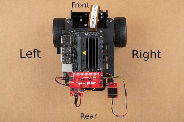
Figure: JetBot orientation showing Front, Rear, Left, and Right sides
Step 1: Chassis Base Assembly
Observe how the motors and ball caster are mounted to the chassis base plate. Note the placement and wiring of the motors.
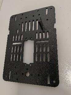
Figure 1: JetBot chassis base plate showing motor mounting holes
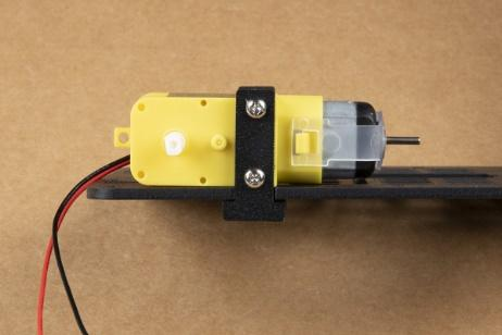
Figure 2: DC motor with wiring harness attached
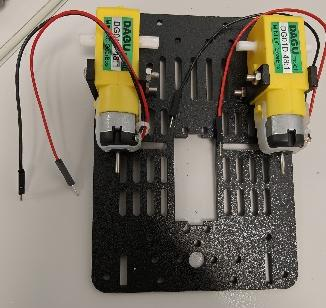
Figure 3: Both motors mounted on the chassis
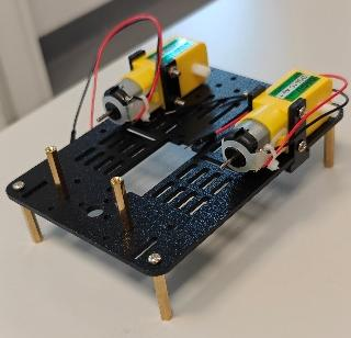
Figure 4: Ball caster installed at the rear for stability
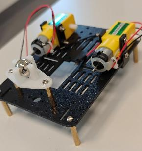
Figure 5: Battery holder bracket attached to chassis
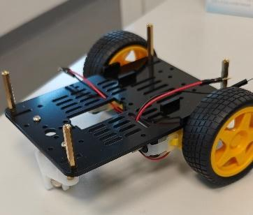
Figure 6: Completed base assembly with wheels attached
Step 2: Camera Mount Assembly
Observe the camera mounting bracket and how the IMX219 camera module is secured in position for forward-facing vision.
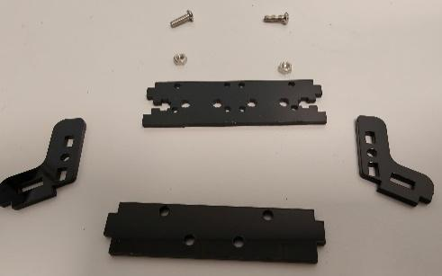
Figure 7: Camera mounting bracket components
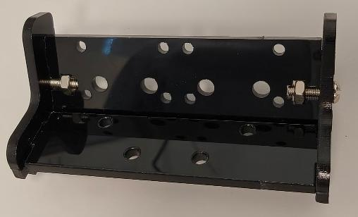
Figure 8: Camera mounting bracket assembled
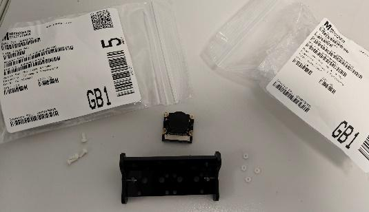
Figure 9: IMX219 camera module secured to bracket
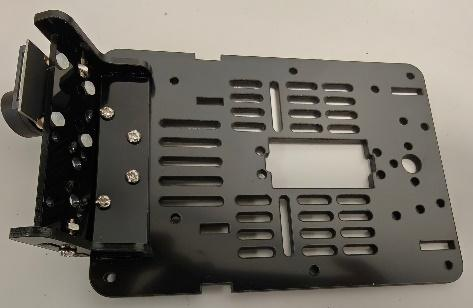
Figure 10: Camera mount attached to chassis front
Step 3: Power System Installation
Observe how the power bank is secured to the chassis using dual-lock fasteners and how the power cable routing is managed.
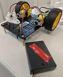
Figure 11: Charmcast 10400mAh power bank positioned on chassis
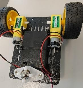
Figure 12: Power bank secured with cable ties and dual-lock
Step 4: Motor Driver Installation
Observe the SparkFun QWIIC Motor Driver board and how motor and battery connections are made. Note the wire color coding: red for positive, black for negative.
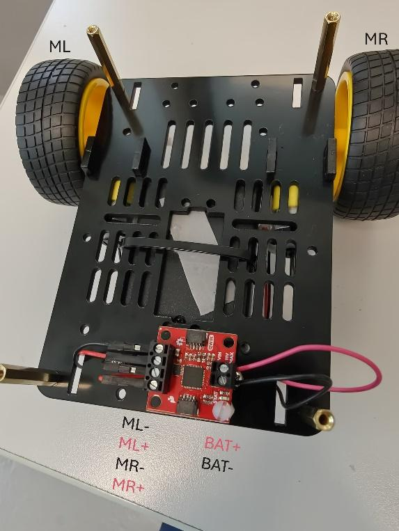
Figure 13: Motor driver with battery and motor connections
Step 5: Power Delivery Cable
Observe the Adafruit USB Type-C PD to barrel jack cable that provides 9V 5A power from the power bank to the Jetson.
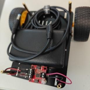
Figure 14: USB-C PD to barrel jack power cable
Step 6: NVMe SSD Installation
Observe how the Lexar NM620 M.2 NVMe SSD is installed in the M.2 Key M slot on the underside of the Jetson board. This provides high-speed storage for the operating system and applications.
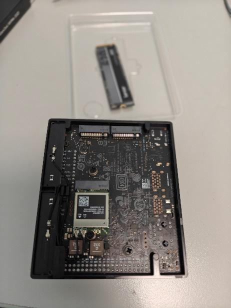
Figure 15: M.2 Key M slot location on Jetson Orin Nano
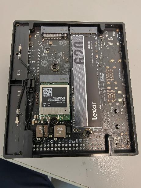
Figure 16: NVMe SSD inserted into M.2 slot
Step 7: Jetson Mounting
Observe how the Jetson Orin Nano is mounted on the upper deck of the chassis using standoffs and secured with adhesive.
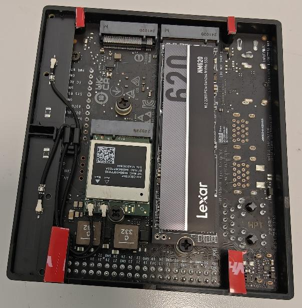
Figure 17: Jetson Orin Nano positioned on chassis
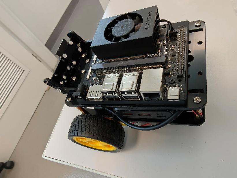
Figure 18: Jetson secured with proper cooling clearance
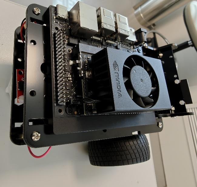
Figure 19: Side view of complete JetBot assembly
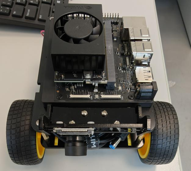
Figure 20: Front view showing camera and motor placement
Step 8: QWIIC Connections
Observe the SparkFun QWIIC pHAT V2.0 mounted on the GPIO header and the QWIIC cable connections to the OLED display and motor driver.
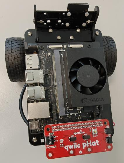
Figure 21: QWIIC pHAT installed on GPIO header
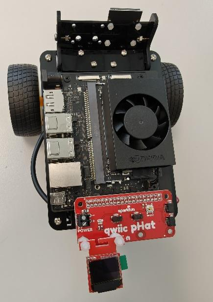
Figure 22: QWIIC pHAT with Micro OLED display connected
Step 9: Final Cable Connections
Observe the camera ribbon cable connection and the QWIIC cable daisy-chain from pHAT → OLED → Motor Driver.
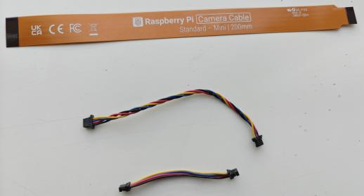
Figure 23: Camera and QWIIC cable routing
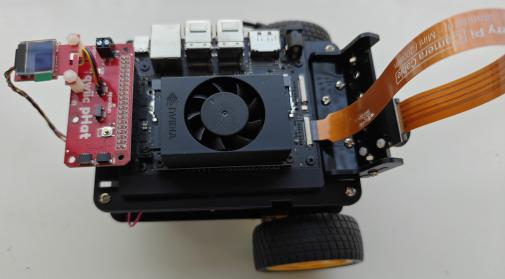
Figure 24: Complete cable management showing all connections
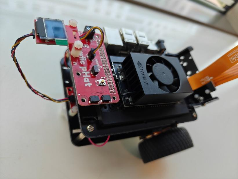
Figure 25: Final assembled JetBot ready for operation
- Chassis kit with motors and wheels
- Jetson Orin Nano Developer Kit
- NVMe SSD (Lexar NM620)
- Power bank (Charmcast 10400mAh)
- Camera (IMX219 8MP)
- QWIIC Motor Driver
- QWIIC pHAT V2.0
- Micro OLED Display
- USB-C PD power cable
Part D: System Capabilities Demonstration (15 minutes)
Your lab instructor will demonstrate the basic capabilities of the JetBot system. Observe and document the following:
Demonstration Checklist:
- Boot Process: Observe the system startup sequence and OLED display initialization
- Camera Functionality: View the camera output and image quality
- Motor Control: Watch basic movement commands (forward, backward, turning)
- Network Connectivity: Understand how to access the JetBot via web interface
- Resource Monitoring: View CPU/GPU usage and temperature during operation
✅ Laboratory Completion
By completing this lab, you have gained familiarity with the hardware platform you'll use throughout the semester. You understand the component selection rationale, recognize the major system components, and have seen the assembly process that created your working JetBot. In upcoming labs, you'll program this system to perform increasingly sophisticated AI tasks.
Lab Materials & References
📚 Reference Documents
| Document | Description | Link |
|---|---|---|
| References Document | Comprehensive list of references and citations | 📄 DOCX |
| Assembly Guide | Complete JetBot assembly instructions with photos | |
| Software Installation Guide | JetPack SDK and Docker environment setup | |
| Jetson Specification | Detailed hardware specifications and pinouts | 📄 DOCX |
| Getting Started Guide | First-time setup and configuration instructions | 📄 DOCX |
| NVIDIA Getting Started | Official NVIDIA documentation | 🔗 Link |
| SparkFun Assembly Guide | Original SparkFun JetBot assembly instructions | 🔗 Link |
🔧 Hardware Components
The following image shows all components required for the JetBot assembly:
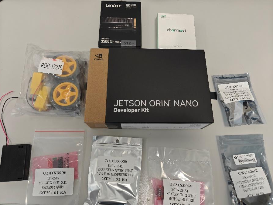
Figure: Complete set of Jetson Orin Nano JetBot components
Each JetBot station includes:
- NVIDIA Jetson Orin Nano Developer Kit
- Lexar NM620 M.2 2280 PCIe Gen3x4 NVMe SSD (512GB)
- Charmcast PowerBank 10400mAh (Model: W1052)
- SparkFun JetBot Chassis Kit V2 (ROB-17279)
- SparkFun QWIIC PHAT V2.0 (DEV-15945)
- SparkFun QWIIC Motor Driver (ROB-15451)
- SparkFun Micro OLED Breakout QWIIC (LCD-22495)
- IMX219-200 8MP Camera with 200° FOV
- Adafruit USB Type-C 3.1 PD to 5.5mm Barrel Jack Cable (9V 5A)
🔩 JetBot Chassis Kit Components
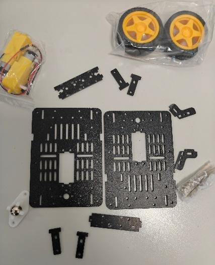
Figure: SparkFun JetBot Chassis Kit V2 components
The chassis kit includes:
- Chassis base plates and mounting brackets
- Two DC motors with wires
- Two wheels and ball caster assembly
- Camera mount brackets and battery holder
- Screws, standoffs, and hardware
Lab Report Requirements
Students must submit a comprehensive lab report demonstrating their understanding of hardware platforms for edge AI applications. The report should showcase knowledge acquired through component identification, platform comparison analysis, and system observation.
Submit your completed lab report by [Insert Deadline - Typically 1 week after lab session]. Late submissions will be penalized according to course policy (10% per day, maximum 3 days).
Report Structure
Your lab report must include the following sections:
1. Title Page (5 points)
- Lab title, your name, student ID, date, course name, and instructor name
- Professional formatting with clear headers and page numbers
2. Learning Objectives (5 points)
- List all learning objectives
- Briefly explain why each is important for embedded AI systems
3. Pre-lab Quiz Results (10 points)
- Include screenshot or summary showing completed quiz
- For any questions answered incorrectly, provide correct answer with explanation
4. Platform Comparison Analysis (20 points)
Complete comparison of Arduino, Raspberry Pi, and Jetson Orin Nano:
- Create detailed comparison table with specifications
- Provide at least two real-world application examples for each platform
- Explain trade-offs between cost, power, and performance
- Answer the discussion prompt about smart doorbell design
5. Component Identification (20 points)
- Include hand-drawn or digital diagram of Jetson Orin Nano
- Label at least 8 major components with descriptions of their functions
- Create comprehensive component list from assembly walkthrough
6. Assembly Understanding (15 points)
- Describe purpose of each major assembly step
- Explain how components connect (motors, camera, QWIIC chain)
- Discuss importance of proper assembly order and cable management
7. System Demonstration Observations (15 points)
- Document observations from instructor's system demonstration
- Note interesting behaviors or performance characteristics
- List at least three questions or ideas for future experiments
8. Conclusion (10 points)
- Summarize key learnings about hardware platform selection
- Reflect on understanding of Jetson Orin Nano and JetBot
- Discuss how this foundation will help in upcoming labs
📋 Submission Checklist
Before submitting, ensure you have:
- ✓ Completed all eight required report sections
- ✓ Included clear diagrams and properly labeled components
- ✓ Answered all discussion questions with supporting analysis
- ✓ Documented system demonstration observations thoroughly
- ✓ Created detailed platform comparison table
- ✓ Formatted report professionally with clear section headers and page numbers
- ✓ Referenced all sources and materials used
- ✓ Proofread for grammar, spelling, and technical accuracy
- ✓ Verified all images are clear, properly labeled, and referenced in text
- ✓ Included your name and student ID on all pages
📤 Submission Format
- File Format: Submit report as PDF document (required)
- File Naming Convention:
- Format:
Week1_[YourLastName]_[StudentID].pdf - Example:
Week1_Ahmed_202012345.pdf
- Format:
- Submission Method: Upload to University LMS (Blackboard/Moodle)
- Page Limit: 8-12 pages recommended (excluding title page)
- Formatting Guidelines:
- Font: Times New Roman 12pt or Arial 11pt
- Spacing: 1.5 line spacing
- Margins: 1 inch on all sides
- File Size Limit: Maximum 50MB
- If exceeded, compress images or use PDF compression tools
- Ensure PDF is searchable text, not scanned images
- Ensure PDF is searchable and not password-protected
- All diagrams must be clearly visible and properly labeled
- Include references to all figures and tables in your text
- Make sure all technical explanations are accurate
- Verify that all sections are complete before submission
📊 Grading Rubric
| Component | Points | Criteria |
|---|---|---|
| Title Page | 5 | Complete, professional formatting |
| Learning Objectives | 5 | Clear, comprehensive explanation |
| Pre-lab Quiz | 10 | Completed with corrections for missed questions |
| Platform Comparison | 20 | Detailed analysis with examples and discussion |
| Component Identification | 20 | Accurate diagram and comprehensive component list |
| Assembly Understanding | 15 | Clear explanation of assembly process and rationale |
| Demonstration Observations | 15 | Thoughtful observations and questions |
| Conclusion | 10 | Reflective, insightful summary |
| Total | 100 |
Grading Notes:
- All diagrams must be clear and properly labeled
- Technical explanations should be accurate and demonstrate understanding
- Report must be professionally formatted with proper sections
- Platform comparison must include practical examples
- Late penalty: 10% per day (up to 3 days)
- Plagiarism will result in zero credit
References & Additional Resources
Official Documentation
- NVIDIA Jetson Orin Nano: Developer Kit User Guide
https://developer.nvidia.com/embedded/learn/get-started-jetson-orin-nano-devkit - SparkFun JetBot: Assembly Guide for SparkFun JetBot AI Kit V2.0
https://learn.sparkfun.com/tutorials/assembly-guide-for-sparkfun-jetbot-ai-kit-v20 - JetPack SDK: NVIDIA JetPack Documentation
https://developer.nvidia.com/embedded/jetpack
Hardware Platforms
- Arduino: Official Arduino Documentation
https://www.arduino.cc/en/Guide - Raspberry Pi: Official Raspberry Pi Documentation
https://www.raspberrypi.com/documentation/ - Comparing Platforms: "Choosing the Right Hardware Platform for IoT" (IEEE IoT Journal)
Edge AI Computing
- Edge AI Fundamentals: NVIDIA Developer Blog - "What Is Edge AI?"
https://developer.nvidia.com/blog/what-is-edge-ai/ - Tensor Cores: Understanding NVIDIA Tensor Core Technology
NVIDIA Technical Brief on Tensor Core Architecture - TensorRT: High-Performance Deep Learning Inference
https://developer.nvidia.com/tensorrt
Books and Textbooks
- Monk, S. (2013). Programming the Raspberry Pi: Getting Started with Python. McGraw-Hill Education.
- Barrett, S. F. (2020). Arduino Microcontroller Processing for Everyone! Springer.
- Patterson, J., & Gibson, A. (2017). Deep Learning: A Practitioner's Approach. O'Reilly Media.
- Halfacree, G. (2018). The Official Raspberry Pi Beginner's Guide. Raspberry Pi Press.
Video Tutorials
- NVIDIA AI Courses: Deep Learning Institute (Free courses on edge AI)
https://www.nvidia.com/en-us/training/ - JetBot Examples: NVIDIA JetBot GitHub Repository with Jupyter Notebooks
https://github.com/NVIDIA-AI-IOT/jetbot - JetBot Orin Nano (UAEU): Hardware Assembly Guide and Video Demonstrations for the Jetson Orin Nano JetBot Platform
https://github.com/moatazsawi/jetbot-orin/tree/main/docs
💡 Tips for Success
- Review the comparison table carefully - it will help you understand platform selection
- Take detailed notes during the component identification and demonstration
- Ask questions if you don't understand a component's purpose
- Think about how the assembly relates to the system's functionality
- Start your lab report early - don't wait until the last day
- Connect concepts from this lab to your prior electronics knowledge
- Consider how you might use these platforms in your own projects
Getting Help
If you have questions or need assistance:
- Instructor: Dr. Mohammad Al Bataineh - faculty.uaeu.ac.ae/mffbataineh
- Office Hours: Check course LMS for schedule
- Lab TAs: Available during lab sessions for immediate questions
- Discussion Forum: Post questions on the course LMS
- Email: Contact instructor for specific clarifications